
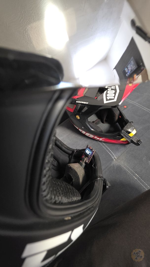
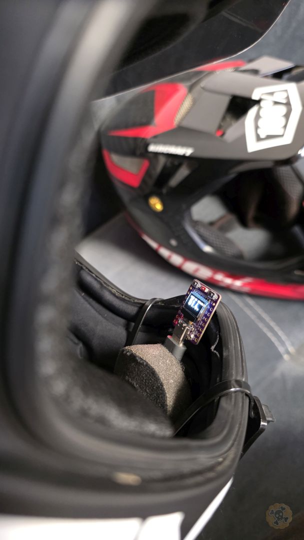
Discover MAD32 EVmo, the world’s smallest advanced dashboard for VESC based on the ESP32-C3 Super Mini with a 0.42″ OLED display. This compact module features a wireless VESC Tool bridge, real-time JBD BMS monitoring (up to 24S), GPS tracking, and a unique MAD32 IO system for wireless accessory control.
ESP32 C3 Oled on ALI: s.click.aliexpress.com/e/_c2wHTWsR & s.click.aliexpress.com/e/_c3UrLCcf
TENSTAR T-Display ESP32-D0WD: s.click.aliexpress.com/e/_c41PYXe3
JBD Smart BMS 8<>14S s.click.aliexpress.com/e/_c45HXOxh
JBD Smart BMS 10<>16S s.click.aliexpress.com/e/_c3A8Kcyb
Mini Advanced Dashboard
ESP32-C3 OLED 0.42″ | VESC RX TX | JBD BMS Monitor (24S) | IO control | GPS
MAD32 EVmo (Mini Advanced Dashboard EVmo) is a compact, wireless dashboard module designed for electric vehicles powered by VESC controllers. It features a bright OLED display showing real-time telemetry data and supports Bluetooth connectivity for both VESC Tool app and BMS monitoring (up to 24S).
Perfect for:
- 🛹 Electric Skateboards & Longboards
- 🛴 E-Scooters & Electric Kick Scooters
- 🚲 E-Bikes & Electric Bicycles
- 🏎️ DIY Electric Vehicles with VESC
- ⚡ Any VESC-powered electric vehicle
🎯 Key Capabilities
Acts as BLE server (NRF UART Service) for wireless connection to VESC Tool app on smartphone, tablet, or PC. Configure and monitor your VESC controller without cables. Requires wired UART connection to VESC.
Connects to remote VESC BT module as BLE client and displays its telemetry. Perfect for dual-motor setups or monitoring a second vehicle wirelessly.
WiFi P2P communication between modules (up to 100m range). Configure via WiFi AP “Pirate.AC” (captive portal) with editable HTML templates stored in LittleFS. Master sends VESC data to Slave display. Network credentials: “piratewashere” (default).
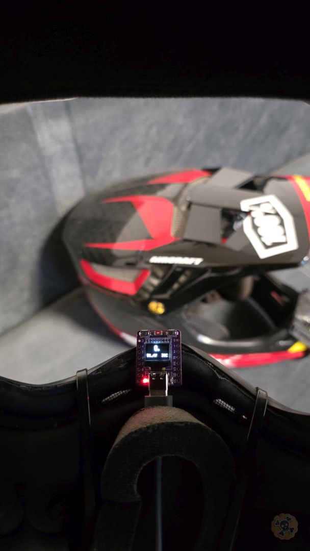
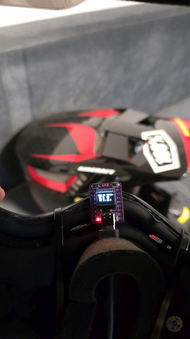
Bright, high-contrast display with 4 customizable screens showing battery voltage, power (watts), temperature, speed, and input signals. Switch screens with onboard button.
Monitor battery pack via Bluetooth: state of charge (SOC%), voltage, current, power, temperature, and individual cell voltages (up to 24S). Cells with 0V are hidden automatically. Helps detect weak or unbalanced cells.
VESC BT RX – BLE client (receive from remote VESC BT) | VESC BT TX – BLE server (VESC Tool bridge) | OFF – VESC disabled
MAD32 IO Mode (3 options – independent):
OFF – MAD32 IO disabled | Master – ESP-NOW TX | Slave – ESP-NOW RX
Main (voltage + mode), Watts+Temp, Power (V+W), Inputs (ADC/PPM). Optional BMS screens show pack status and cell voltages (up to 24S). Screen count adapts automatically to cell configuration.
All configuration (mode, BT devices, rotation, BMS settings) saved to flash memory. Survives power off and restarts. Auto-reconnects to saved devices on boot.
Configure MAD32 IO network via WiFi AP. HTML templates stored in LittleFS (editable without recompiling). Automatic fallback to PROGMEM if filesystem unavailable. Default credentials: “piratewashere”.
💡 How It Works
Connect ESP32-C3 to VESC via 4-wire UART (TX, RX, 3.3V, GND). Module draws power from VESC 3.3V output.
Hold BOOT button (2s) to enter config menu. Select operating mode, pair BT devices, enable BMS if needed.
Display shows real-time telemetry. Press BOOT button briefly to cycle through screens. Module auto-connects to saved devices.
⚙️ Technical Specifications
✅ What You’ll Need
- MAD32 EVmo module (ESP32-C3 with OLED display)
- VESC controller with UART port (4-pin connector)
- 4 wires for connection (TX, RX, 3.3V, GND)
- USB-C cable for initial firmware flashing
- Computer with NodeMCU-PyFlasher installed
- Optional: JBD/Xiaoxiang BMS for battery monitoring
📝 Step-by-Step Setup
- Flash Firmware to ESP32-C3Connect ESP32-C3 to your computer via USB-C. Use NodeMCU-PyFlasher to flash the
MAD32_EVmo_V1a.binfile. Settings: Baud 115200, Flash Mode DIO, Address 0x0, Erase flash: Yes.
→ See “Flashing” tab for detailed instructions - Wire ESP32-C3 to VESCConnect 4 wires from ESP32-C3 to VESC UART port:
3.3V → 3.3V (power) | GND → GND (ground) | GPIO21 → RX (ESP TX to VESC RX) | GPIO20 → TX (ESP RX to VESC TX)
→ See “Wiring” tab for diagram - First Power-OnTurn on VESC. The module will show splash screen:
Pirate.AC → MAD32 EVmo → Firmware:V1a
Then display switches to Main Screen showing mode and battery voltage. - Configure Operating ModesHold BOOT button for 2 seconds to enter Configuration Menu.
VESC Mode (Page 1): VESC BT RX (wireless from remote VESC BT) | VESC BT TX (wired UART + wireless VESC Tool) | OFF
MAD32 IO Mode (Page 7): OFF (default) | Master (ESP-NOW TX) | Slave (ESP-NOW RX)
→ See “Configuration” tab for detailed menu navigation - Optional: Enable BMS MonitoringIn config menu, navigate to BMS Feature → ON.
Then go to BMS Status page and hold BOOT (2s) to search for your JBD/Xiaoxiang BMS.
Select device from list and hold BOOT again to save. Module will auto-connect on next boot. - Save Settings & ExitNavigate to Save & Exit page in config menu.
Hold BOOT button (2s) to save all settings and restart module. Settings are stored in flash memory and persist after power off.
🎮 Daily Operation
📱 Connect VESC Tool
1. Open VESC Tool app on phone/tablet/PC
2. Scan for Bluetooth devices
3. Connect to module (name: User1-6 or device name)
4. Configure VESC wirelessly
📺 View Telemetry
1. Short press BOOT to cycle screens
2. Screen 1: Battery voltage + mode
3. Screen 2: Power (W) + Temperature
4. Screen 3: Voltage + Power (large)
5. Screen 4: ADC/PPM inputs
🔋 Monitor BMS
1. Enable BMS Feature in config menu
2. Pair with JBD/Xiaoxiang BMS
3. View 3 additional screens:
• BMS Main (V, SOC%, A, W, °C)
• Cells 1-8 voltages
• Cells 9-16 voltages
⚠️ Important Notes
- Power: ESP32-C3 operates at 3.3V. DO NOT connect 5V to GPIO pins!
- UART: Make sure UART is enabled in VESC Tool settings (baud rate 115200)
- MAD32 IO Pairing: When using MAD32 IO Mode (Master or Slave), navigate to Page 8 (MAD32 IO WiFi) to configure network via captive portal “Pirate.AC” (both devices need matching network name)
- BMS: Only JBD/Xiaoxiang protocol BMS are supported (3S-24S configurations)
- Reset: To factory reset, hold BOOT while powering on until “Factory Reset” appears
Free tool for Windows and macOS – download from GitHub Releases
Step-by-Step Instructions
- Download and Install NodeMCU-PyFlasherDownload the latest release from GitHub. For Windows, use the
.exefile. For macOS, use the.dmgfile. No installation required – just run it. - Connect ESP32-C3 to your ComputerUse a USB-C cable to connect the ESP32-C3 module to your computer. Make sure it’s a data cable, not just a charging cable. The module should be recognized automatically.
- Select COM PortIn NodeMCU-PyFlasher, click the
Serial portdropdown and select the COM port for your ESP32. On Windows it’s usuallyCOM3,COM4, etc. On macOS it’s/dev/cu.usbserial-xxx. - Select Firmware FileClick
Browseand select theMAD32_EVmo_V1a.binfile that you received. - Configure Flash SettingsSet the parameters as shown below. These settings are critical for proper flashing!
- Flash the FirmwareClick
Flash NodeMCUbutton. Wait for the process to complete. You should see “Finished” message when done. The module will restart automatically.
⚙️ Required Flash Settings
Important!
The flash address must be set to 0x0 (zero). The BIN file contains bootloader, partitions, and firmware merged together. Using wrong address will result in non-working module.
✅ Troubleshooting
- COM port not visible? – Install CH340/CP2102 USB driver for your system
- Connection failed? – Try holding BOOT button while connecting USB, then release
- Flash failed? – Try lower baud rate (57600) or different USB cable
- Module not starting? – Verify flash address is 0x0 and re-flash with “Erase flash” enabled
WARNING: 3.3V Logic Level!
ESP32-C3 operates at 3.3V logic. DO NOT connect 5V directly to ESP32 pins! Use 3.3V from VESC or a voltage regulator.
🅰 VESC Wiring VESC Mode = VESC BT TX | GPIO20, GPIO21
- Power 3.3V
- Ground GND
- UART RX GPIO20
- UART TX GPIO21
OLED SDA: GPIO5
OLED SCL: GPIO6
BOOT Button: GPIO9
- 3.3V Output 3.3V
- Ground GND
- UART TX TX
- UART RX RX
Standard 4-pin
header on VESC board
115200🅱 GPS Wiring Always GPIO3 (RX) / GPIO4 (TX) — works with any VESC Mode
- Power 3.3V
- Ground GND
- GPS RX ← GPS TX GPIO3
- GPS TX → GPS RX GPIO4
OLED SDA: GPIO5
OLED SCL: GPIO6
BOOT Button: GPIO9
- VCC 3.3V
- GND GND
- TX (→ ESP RX) TX
- RX (← ESP TX) RX
BN-180 / BN-220
or any NMEA module
📋 Configuration Pages
Hold BOOT button 2s to enter config menu. Pages appear in this order (short press = next page, hold 2s = action):
Short press: cycle VESC BT RX → VESC BT TX → OFF
Hold 2s: start search → Short press: scroll devices → Hold 2s: save device
Short press: toggle Normal/180°
Short press: toggle ON/OFF
Hold 2s: start search → Short press: scroll devices → Hold 2s: save device
Short press: cycle OFF → Master → Slave
Hold 2s: toggle captive portal “Pirate.AC” (WiFi config for network & GPIO settings)
Hold 2s: save all settings → device restarts automatically
📝 Important Notes:
- Two Independent Settings: VESC Mode (Page 1) and MAD32 IO Mode (Page 7) are SEPARATE configuration options that can be combined in various ways
- VESC Mode cycling (Page 1): VESC BT RX → VESC BT TX → OFF → (repeat). Short press to change
- MAD32 IO Mode cycling (Page 7): OFF → Master → Slave → (repeat). Separate setting from VESC Mode
- VESC Mode options: VESC BT RX (BLE client to remote VESC BT), VESC BT TX (BLE server for VESC Tool), OFF (VESC disabled)
- MAD32 IO options: OFF (no network), Master (BLE client for remote GPIO control), Slave (BLE server with GPIO outputs)
- VESC BT Status (Page 2): Only shown when VESC Mode = BT RX. Hold 2s to search for remote VESC BT modules
- BMS Status (Page 5): Only shown when BMS Feature = ON. Hold 2s to search. Supports 3S-24S with auto-reconnect (scan: 5s, retry: 10s)
- MAD32 IO WiFi (Page 8): Only shown when MAD32 IO Mode ≠ OFF. Captive portal “Pirate.AC” for network/GPIO config (default: “piratewashere”)
- Display Screens: 3 VESC screens (Main, Watts+Temp, Inputs) when VESC enabled. BMS screens (1-3) when BMS enabled. Screen count adapts to cell count (12S = 2 screens, 24S = 3 screens)
- Settings saved to NVS flash memory and persist after restart
- Module automatically restarts after saving configuration
🎯 What is VESC?
VESC (Vedder Electronic Speed Controller) is an open-source motor controller designed by Benjamin Vedder. It’s widely used in electric skateboards, e-bikes, and other electric vehicles for its advanced features like FOC (Field Oriented Control), regenerative braking, and comprehensive telemetry.
🔄 VESC Modes (Page 1)
The VESC Mode setting (Page 1 in config menu) controls how MAD32 EVmo connects to and communicates with VESC motor controller. Three options available:
UART → BLE Server (Wireless Bridge)
• ESP32 connected via UART to local VESC
• Acts as BLE server for VESC Tool app
• Enables wireless VESC Tool configuration
• Requires 4-wire UART connection (TX, RX, 3.3V, GND)
BLE Client → Remote VESC BT
• Connects to remote VESC BT module wirelessly
• No UART wiring required (100% wireless)
• Receives telemetry data via Bluetooth BLE
• Perfect for monitoring 2nd vehicle or remote VESC
VESC Functionality Disabled
• No VESC communication (UART or BLE)
• Device can work as BMS-only monitor
• Saves power and BLE resources
• Shows “Turn On FEATURES” if BMS also disabled
🔌 VESC Wiring Diagram
- Power 3.3V
- Ground GND
- UART RX GPIO20
- UART TX GPIO21
OLED SDA: GPIO5
OLED SCL: GPIO6
BOOT Button: GPIO9
- 3.3V Output 3.3V
- Ground GND
- UART TX TX
- UART RX RX
Standard 4-pin
header on VESC board
115200📊 Real-Time Telemetry
Real-time power consumption in watts, battery voltage, and input current. Essential for range estimation and efficiency optimization.
MOSFET and motor temperature tracking. Prevents overheating and thermal damage to your controller.
ADC1, ADC2, and PPM signal monitoring. Debug throttle issues and verify remote control signals.
⏱️ OSD Priority Intervals
Optimized timing intervals for responsive real-time dashboard display:
📺 Display Screens (3 VESC Screens)
Screen cycling:
• All modes: Main → Watts+Temp → Inputs
Button: Short press to cycle through screens
🎯 What is BMS?
BMS (Battery Management System) protects your battery pack from overcharge, over-discharge, overcurrent, and cell imbalance. MAD32 EVmo supports JBD/Xiaoxiang BMS via Bluetooth for real-time battery monitoring and cell balancing verification.
📊 Battery Pack Telemetry
Total voltage, state of charge (SOC%), current flow (charge/discharge), power output, and pack temperature.
Monitor each cell (up to 24S) separately. Cells with 0V are hidden automatically. Identify weak cells, detect imbalance issues, and verify proper balancing.
Current direction indicator (+ charging / – discharging), power in watts, and remaining capacity estimation.
✅ Supported BMS Models
- JBD/Xiaoxiang BMS: SP04S, SP05S, SP10S, SP12S, SP13S, SP14S, SP15S, SP16S, SP20S, SP21S, SP24S
- Protocol: Xiaoxiang/Overkill Solar BMS (Bluetooth BLE)
- Cell count: 3S to 24S configurations supported (dynamic screen count)
- Connection: Wireless via Bluetooth (no additional wiring needed)
- Auto-reconnect: Automatic BLE scan (5s) and reconnection (10s) after disconnect
📺 Display Screens (Dynamic Count)
Additional screens when BMS Feature ON:
• Screen 5: BMS Main (pack voltage, SOC%, current, power, temperature)
• Screen 6+: Cell voltages (8 cells per screen, up to 24S total)
Smart Display: Screen count adapts automatically to detected cell count (e.g., 12S = 2 screens, 24S = 3 screens). Cells with 0V are hidden automatically.
Access: Cycle through VESC screens first, then BMS screens appear
🎯 What is MAD32 IO?
MAD32 IO is a wireless distributed GPIO control system using BLE (Bluetooth Low Energy). It enables Master devices to remotely control GPIO outputs on Slave devices (lights, relays, actuators, etc.). Perfect for remote lighting control, relay switching, or any wireless GPIO automation.
🔄 MAD32 IO Modes (Page 7)
Three MAD32 IO modes available, configured via Page 7 in the config menu:
MAD32 IO Network Disabled
• No ESP-NOW communication
• WiFi radio turned off (saves power)
• Standard single-device operation
• Default mode for most users
BLE Client (Remote Control)
• Scans for Slave devices advertising MAD32 IO service
• Connects to Slaves via BLE and validates credentials
• Reads GPIO slot information from Slaves
• Sends toggle commands to control Slave GPIO remotely
• Can control multiple Slaves simultaneously
BLE Server (GPIO Control)
• Advertises MAD32 IO service via BLE for Master discovery
• Exposes GPIO slot configuration (up to 3 slots: name, state)
• Controls physical GPIO pins (OUTPUT mode)
• Responds to toggle commands from Master
• Additional ESP32 boards or MAD32 devices
🌐 WiFi Configuration Portal
Captive Portal “Pirate.AC”
Advanced network and GPIO configuration accessible via WiFi AP (Page 8 in config menu, only shown when MAD32 IO Mode ≠ OFF):
- Network Config: Set network name & password (must match on Master and all Slaves)
- Slave GPIO Slots: Define up to 3 GPIO functions (name, pin number, default state, invert logic)
- Editable HTML: Templates stored in LittleFS (data/madio_config.html) – customize without recompiling
- Default Credentials: Network name & password: “piratewashere”
- Access: Navigate to Page 8 in config → Connect smartphone to WiFi “Pirate.AC” → Portal opens automatically
🎮 GPIO Control Features (Slave Mode)
Control headlights, taillights, LED strips (WS2812B), or brake lights. Define GPIO outputs via captive portal.
Switch relays, solenoids, or other actuators. Master can toggle Slave GPIO outputs remotely via button press.
Each Slave device can control up to 3 independent GPIO outputs. Configurable name, pin, default state, and logic inversion.
• Wireless Relay Switching: Master remotely controls Slave relays, solenoids, or actuators
• Multi-Zone Lighting: One Master controls multiple Slave devices with different light zones
• Automated GPIO Control: Master triggers actions on Slave GPIO outputs based on events
✅ BLE Migration Complete (Feb 2026)
All-Bluetooth Architecture: MAD32 IO has been successfully migrated from ESP-NOW to BLE (Bluetooth Low Energy).
This eliminates WiFi/BLE radio conflicts on ESP32-C3 single-radio architecture.
Benefits: Reliable coexistence with other BLE devices (no radio conflicts). Better range, simpler code, no WiFi interference.
🎯 What is GPS Module?
GPS Module integration provides accurate speed tracking, distance measurement, and altitude monitoring independent from motor RPM calculations. Uses external GPS module connected via UART with automatic baud rate detection (4800-115200 bps). Perfect for verifying actual speed vs calculated speed and trip distance tracking.
📡 GPS Configuration (Pages 5-6)
GPS Module is configured via config menu (Page 5 enables/disables, Page 6 sets power mode). Always uses fixed pins GPIO3 (RX) and GPIO4 (TX).
🔌 GPS Wiring Diagram
- Power 3.3V
- Ground GND
- GPS RX ← GPS TX GPIO3
- GPS TX → GPS RX GPIO4
OLED SDA: GPIO5
OLED SCL: GPIO6
BOOT Button: GPIO9
- VCC 3.3V
- GND GND
- TX (→ ESP RX) TX
- RX (← ESP TX) RX
BN-180 / BN-220
or any NMEA module
📊 GPS Data & Features
Real-time speed in km/h from GPS satellites. Independent from motor RPM. Max speed recording for trip analysis.
Total distance traveled in kilometers. Calculated using Haversine formula between GPS coordinates. Trip reset available.
Altitude above sea level in meters. Useful for elevation gain tracking and hill climbing performance analysis.
Number of satellites in view. More satellites = better accuracy. Typically 4+ needed for valid fix.
⚡ Power Modes (Page 6)
🔋 Normal Power Mode
Standard power consumption with balanced performance. Suitable for most use cases. Lower power draw for longer battery life.
⚡ Max Power Mode
Maximum performance mode for best accuracy, speed, and precision. Faster satellite acquisition. Higher power consumption.
🔧 Technical Features
- Auto Baud Rate Detection: Automatically detects GPS module baud rate (4800, 9600, 14400, 19200, 38400, 57600, 115200 bps)
- NMEA Protocol: Uses TinyGPS++ library for parsing NMEA sentences from GPS module
- Fixed Pin Assignment: GPS always uses GPIO3 (RX) and GPIO4 (TX), independent from VESC UART on GPIO20/21
- Trip Data Reset: Reset distance and max speed counters via config menu
- Satellite Status: Visual indication of GPS fix quality (Checking/Waiting Sat/Valid/Error)
- Optional Compass: I2C compass support (QMC5883L/HMC5883L) on GPIO8,10 or shared with OLED (GPIO5,6)
• Beitian BN-180 / BN-220: Compact GPS modules with built-in antenna
• Any NMEA-compatible GPS: Modules outputting standard NMEA sentences via UART
• Connection: 4-wire (GPS TX → ESP32 RX, GPS RX → ESP32 TX, VCC, GND)
⚠️ GPIO Pin Conflicts
ESP32-C3 Limited GPIO Availability: Only GPIO 0-10 and 20-21 available (NO GPIO 11-19).
• GPIO5,6: Reserved for OLED (I2C)
• GPIO9: BOOT button
• GPIO20,21: VESC UART only
• GPIO3,4: GPS module (always fixed)
Note: If using external TFT display (ST7789 76×284), GPIO conflicts may occur with GPS. Choose either GPS or TFT, or use different pin assignments.
🔮 What’s Coming Next
MAD32 EVmo is under continuous development. Below is our roadmap of planned features that will expand the dashboard’s capabilities. These features are in various stages of planning and development. Stay tuned for updates!
✅ Recently Completed (Feb 2026)
Expanded from 16S to 24S cell support. Dynamic screen count adapts automatically to detected cell configuration. Cells with 0V are hidden for cleaner display. Perfect for high-voltage EV builds.
MAD32 IO captive portal HTML now stored in LittleFS (data/madio_config.html). Customize interface without recompiling firmware. Automatic fallback to PROGMEM if filesystem unavailable.
Automatic BLE scan every 5 seconds and connection retry every 10 seconds after BMS disconnect. No manual intervention needed – system reconnects automatically when BMS is back in range.
Cells with 0V voltage automatically hidden from display. Cleaner interface and easier cell monitoring. Screen count adapts to actual cell configuration (e.g., 12S = 2 screens, 24S = 3 screens).
External GPS module via UART with speed tracking, distance measurement, altitude, and satellite count. Fixed pins GPIO3/GPIO4, independent from VESC UART. Power modes: Normal/Max.
Migrated MAD32 IO from ESP-NOW to BLE for distributed GPIO control. Eliminates WiFi/BLE radio conflicts on ESP32-C3. Master/Slave BLE architecture with secure credential validation. Better reliability and coexistence with other BLE devices.
✨ Coming Soon
Mirror telemetry to external displays:
• ST7789 76×284 super-wide color LCD
• Transparent OLED 128×64 for HUD applications
Enable in config menu for dual-screen setup with simultaneous display on both screens.
Control vehicle lighting via ESP-NOW:
• Turn headlights/taillights ON/OFF
• Control LED strips (WS2812B, etc.)
• Change colors and brightness
• Custom lighting patterns
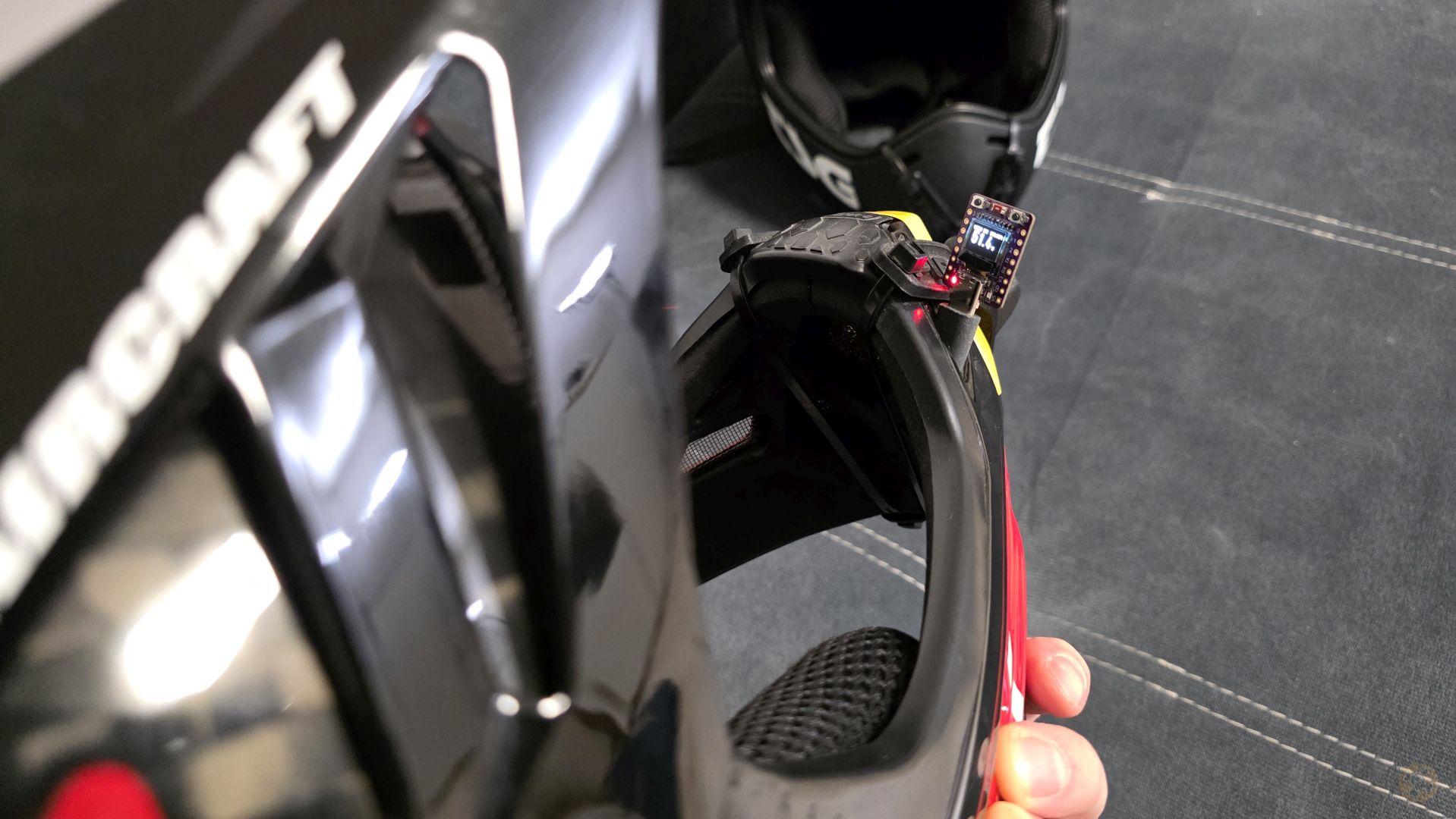
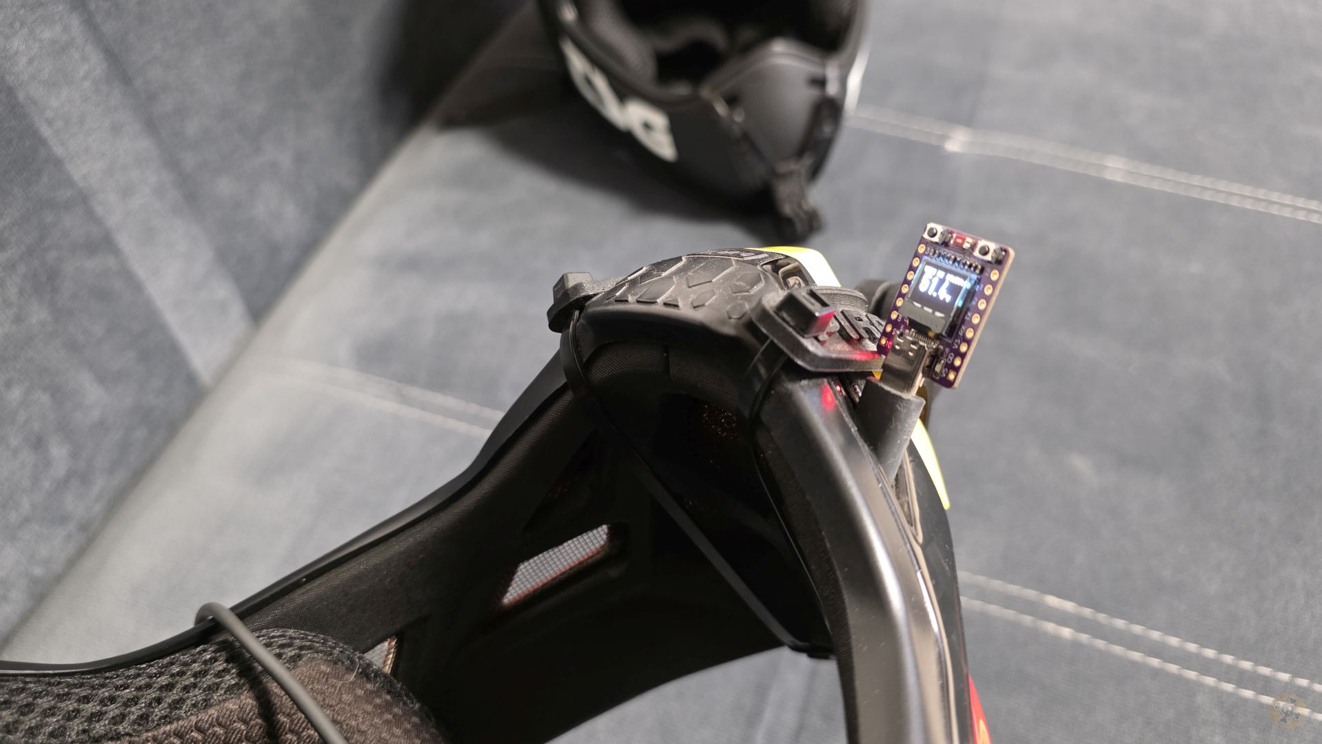
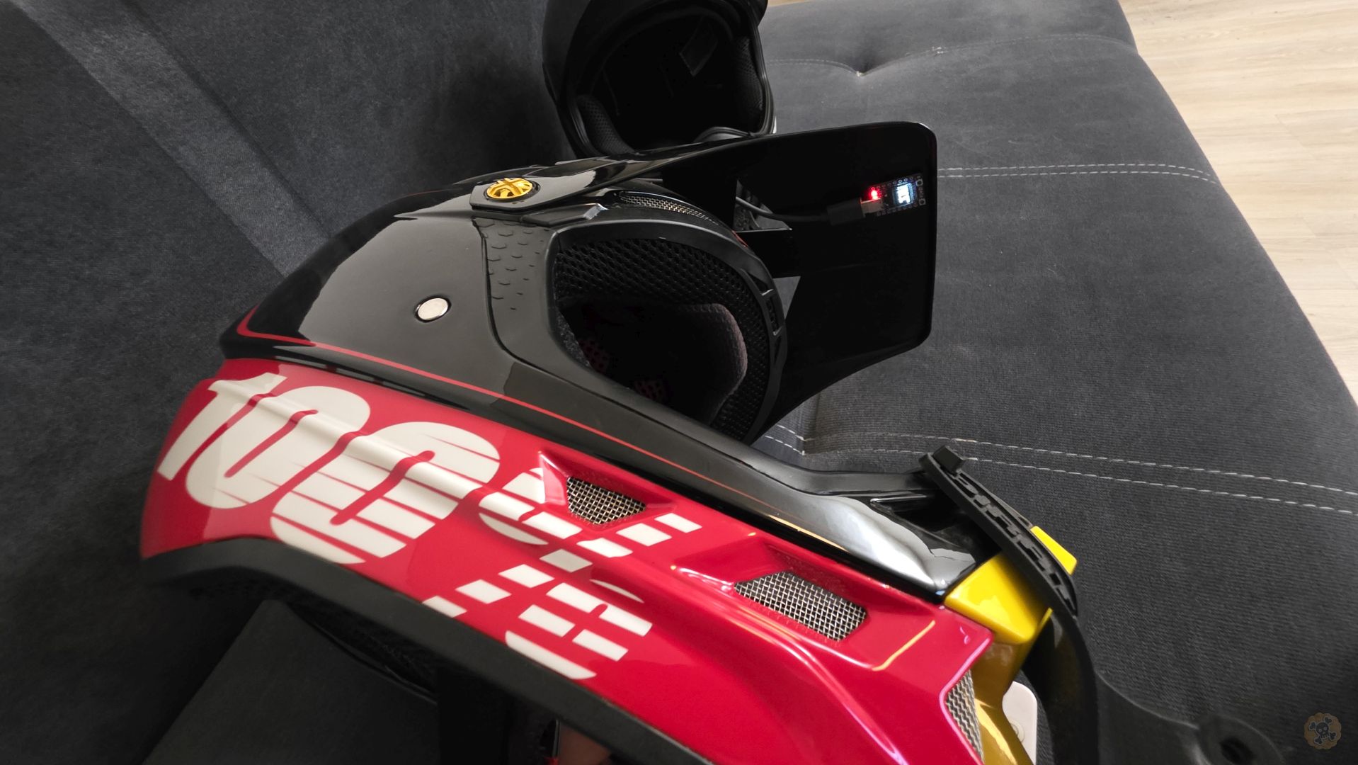
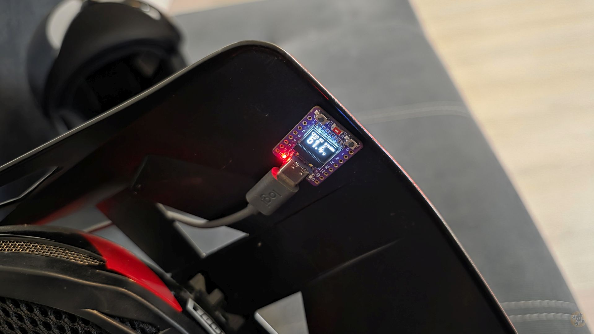
Helmet-mounted gyroscope detects head turning direction and automatically activates turn signals. Wireless communication via ESP-NOW to vehicle lighting system. Enhances safety for night riding.
Connect Magene heart rate sensor via Bluetooth. Display real-time heart rate on dashboard screen. Track fitness levels during rides and monitor cardiovascular performance.
Monitor air quality, temperature, and humidity:
• Air Quality Index (AQI)
• Temperature and humidity
• VOC (Volatile Organic Compounds) detection
• CO2 equivalent (eCO2) levels
Support for KT (Kunteng) bicycle controllers used in e-bike conversion kits. Read telemetry data via UART/serial communication. Expands MAD32 EVmo beyond VESC to e-bike market.
We’re constantly exploring new features and improvements based on community feedback. Have an idea? Let us know! The roadmap evolves with user needs.
📅 Development Timeline
Active coding and testing phase. Expected in next major release.
Feature design complete. Scheduled for future development cycle.
Exploring feasibility, hardware compatibility, and implementation approaches.
💬 Want to Contribute?
MAD32 EVmo welcomes community contributions! Whether it’s feature suggestions, bug reports, or code contributions – your input helps shape the future of this project.
- Feature Requests: Share your ideas for new features
- Bug Reports: Help us improve stability and reliability
- Hardware Testing: Test with different VESC models and BMS types
- Documentation: Improve guides, translations, and tutorials